
To get better performance or lower power consumption for specific applications an acceleration ASIC IP will be added to the traditional SoC design. The ASIC AP, which co-works with the basic processor, can get an extra performance boost or lower power consumption. But, the disadvantages are also obvious. The ASIC IP demands a long design cycle and the redesign of the software stack will cost extra effort. Most importantly, the poor re-usability makes it impossible to upgrade unless you redesign the ASIC IP.
DSA design shows another way to solve this problem using a custom instruction to accelerate the applications instead of using the ASIC IP. DSA design has several advantages:
First, the custom instructions share the same software stack making the software design flexible. Second, it’s easy to upgrade using additional instructions and can easily accelerate the target applications. Third, the logic design effort is much less than with ASIC IP design and integration. Further, with automated design tools, DSA design can rapidly reduce the time to market.
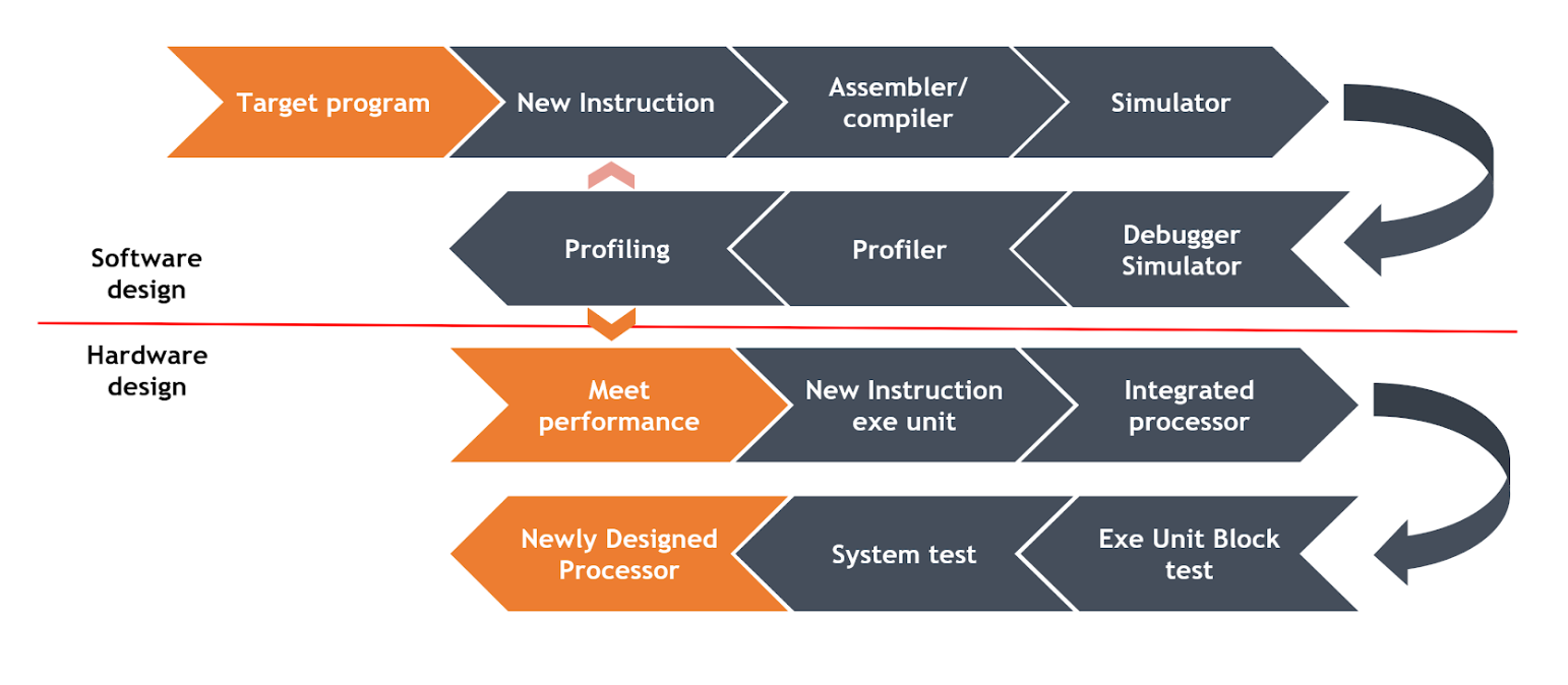
Basic DSA design flow
Above is the illustration of the basic DSA design flow. First, upon obtaining the target program, the designer uses the processor profiling tool to identify the critical part of the application. Then the function can be extrapolated from the instructions to accelerate the target program. As a result, performance goals are achieved with the newly modified profiles.
In the next steps instructions are integrated into the toolchain and recompiled with new information. This enables the new toolchain, including the assembler or compiler, to be successfully re-developed accordingly. Next the designers incorporate a simulator, debugger, or profiler to evaluate the performance in the next round to achieve higher profiling and ultimate optimization.
Once the instruction function is ready, the designers move onto hardware. First, they integrate the instruction execution unit into the baseline processor. The processor should be verified and subsequently signed off. Then they run a verification procedure, which contains an execution unit block and system test. A stable new processor with a DSA accelerating function is now ready. With resources spent on software stack development, hardware design, and verification cycle, it is inevitable to incur extra cost and efforts in collaboration with other engineers. This is one of the biggest challenges of producing DSA design.
T-Head DSA design tool
We present a remedy tool, T-Head DSA design to solve the problems mentioned above in the following figure. The goal of this tool is to achieve a simple and fast DSA flow. The customer should only focus on abstracting the new instructions and check whether they meet the performance goals. The T-Head DSA design tool is structured to encode new instructions, tool chains, and SDKs. Similarly, the tool allows hardware designers to focus on new functions, whereas the T-Head tool targets the processor. Furthermore, to reduce the verification effort further the T-Head DSA design tool will further reduces efforts in verification and creates an environment for testing, accelerating design cycles, and stabilizing processors all at a lower cost.
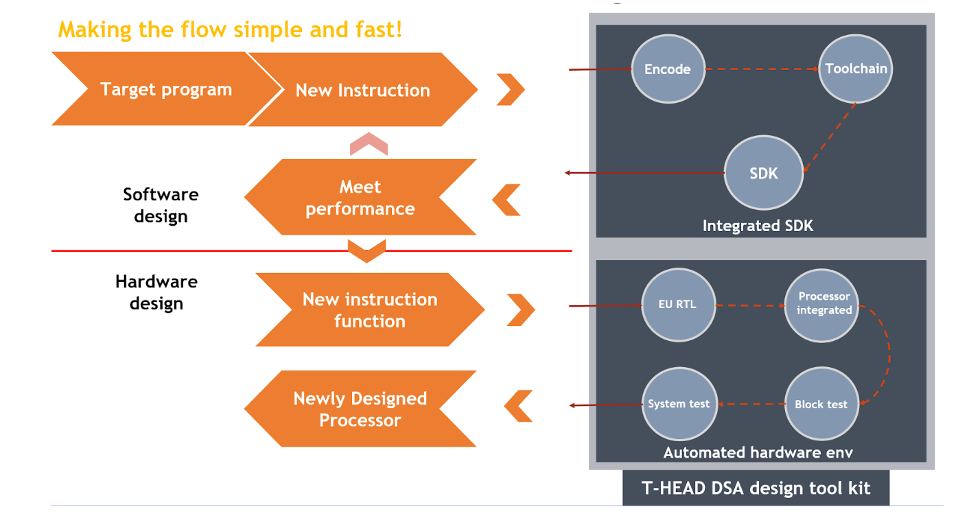
Quick flow
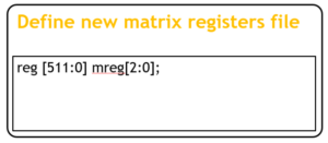
Here is an example of how to use the T-Head DSA design tool to design a new instruction. First, we identify one matrix mac instruction that can accelerate the applications through profiling. To avoid any change in the software stack, we will use a separate register file in the new instruction. We then define a new matrix register file using the simple grammar “reg”. ,register file “mreg” with 8 registers, as shown in the following figure.
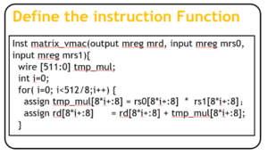
Next defining the new instruction we use simple grammar for (iVerilog and C-like language for function descriptions; for example) two inputs and one output. All operands are matrix register files. The designer implements the function at a higher level than the Verilog language such as “for-loop” to describe a multi-data multiply & accumulative operation.
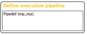
We take the next step to utilize extra information for the tool in translating function into hardware logic. Specifically, we use grammar “pipedef” to add a pipeline register for the “tmp_mul” signal, which will auto-schedule other signals and locals accordingly.
The tool will extract the assembly grammar, collect the information of the operands, and then obtain the bit-numbers of the operands. Then it auto-encodes all the instructions. Lastly, the tool will calculate an optimal opcode for each instruction and use custom2 as the main-op.
Software generation
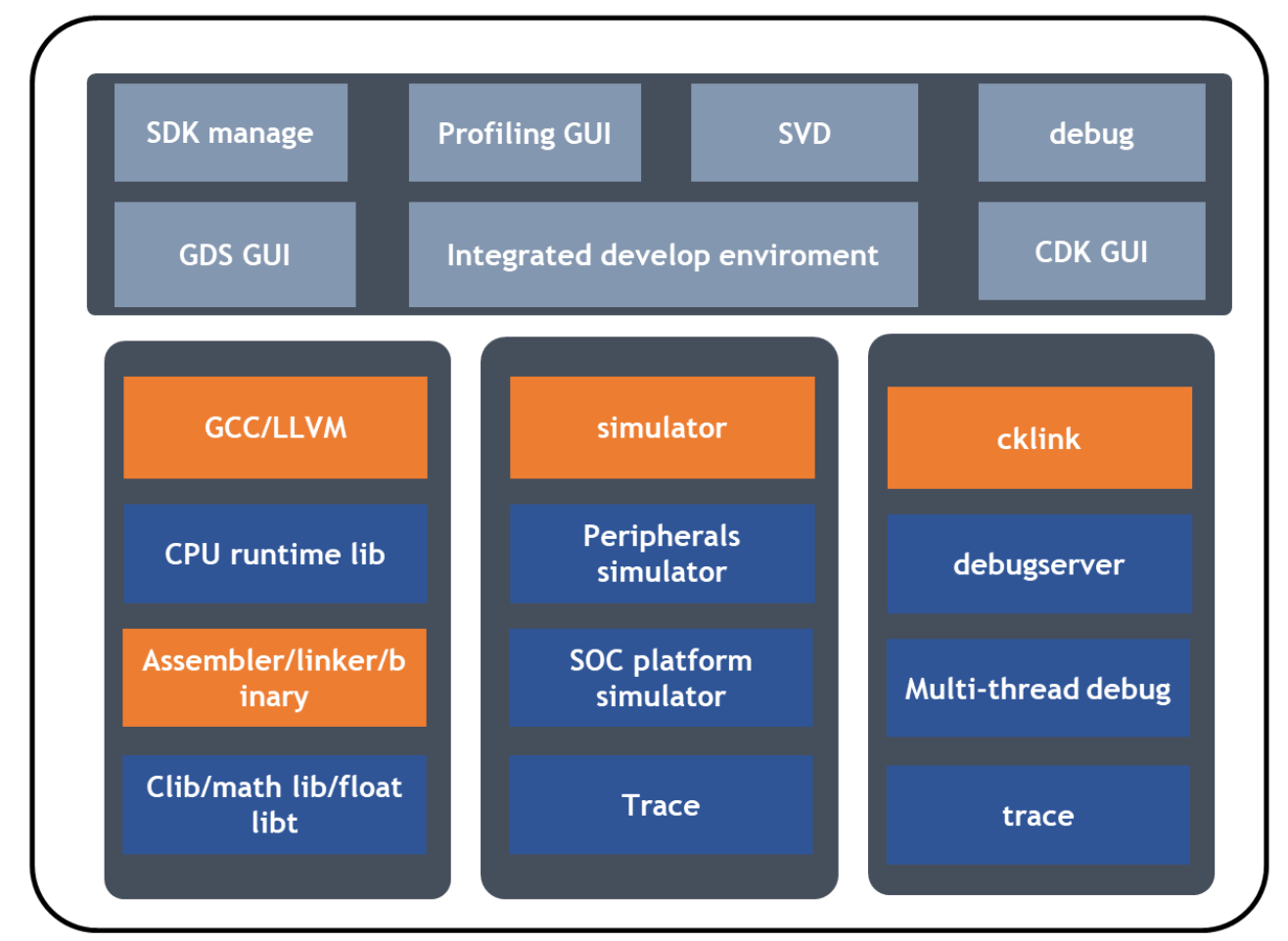
After the instruction is encoded the assembler can be automatically generated. The new instruction will be registered into the compiler so that it allows for programmers to add the new instruction. Furthermore, the DSA tool can be used to generate the simulator, including the cycle-accurate simulator. With the simulator the profiler can get the new simulation information and get another round of software optimization.
Hardware design
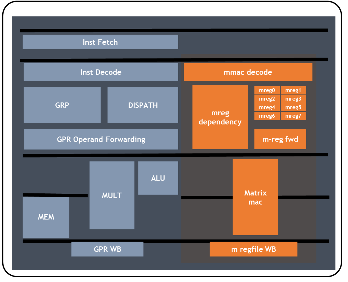
The designer is now ready to set up the flow for hardware. According to the function description and pipeline definition the T-Head DSA design tool will generate the execution unit Verilog RTL code, as shown in the previous figure and auto-schedule the pipeline. The new execution unit will be integrated into the processor pipeline as shown in the following figure. The decode logic will be added to the decoding stage of the processor. In addition to the newly added register file, the issue logic for new instructions and operand forwarding and the result writing back logic will be generated automatically and scheduled in the appropriate pipeline of the baseline processor. Finally, the new processor is ready for verification.
Verification platform
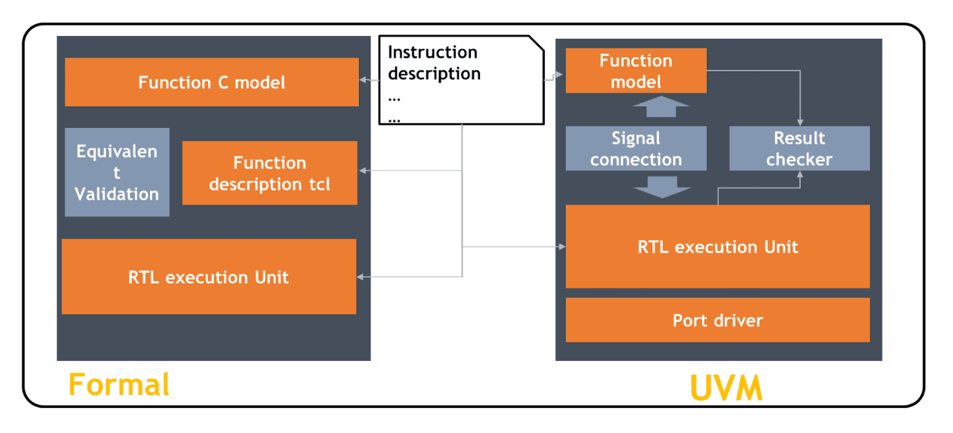
To further reduce the development effort the T-Head DSA design tool can generate the verification environment including the unit test environment for the execution unit, the system test environment for the processor, and the unit test environment including the UVM and formal test. The tool will assemble the function module, port drivers, or result checker for the UVM, which can support random stimulus tests. If the Synopsys formal dpv license is available, a formal test can be launched to test the execution unit. The T-Head DSA design tool can generate the dpv environment and add the formal equivalent checker for full validation of the RTL code and the function model.
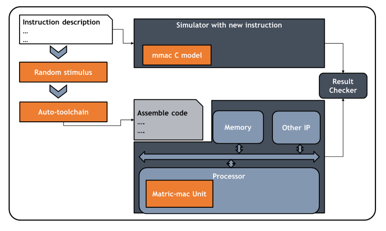
For the system test environment the tool will generate the processor function simulator with new instructions and the environment will deliver an SoC platform with the auto-generated toolchain. The designer can conduct the system test with the assembly code or c-code test stimulus. Furthermore, a random stimulus will be generated by the DSA design tool which includes a basic function test for the processor and the stimulus for new instructions.
With the hands-free verification environment and test stimulus, the designer can easily conduct the test and make sure the design is bugless for signoff.
Above is a quick illustration of the T-Head design tool. The most important feature of the tool is the customizability of the processor. The T-Head design tool delivers rich function blocks that user-defined instructions can use. For the data path customers can add new tightly-coupled memory, I/O ports, register files, or control registers. For the control path, the hardware loop can be added to further accelerate the execution of the critical program code. There are different baseline processors with different performance and costs ready for customers to choose. With all these capabilities, the designer has plenty of choices and methods to accelerate their target function.
The T-Head DSA tool kit helps accelerate processor design innovation, enabling the customer to focus on function acceleration. The tool kit will cover the SDK or processor integration, make the processor design simple and fast, and offer diverse customizability, helping the customer to deliver more suitable, efficient, and better performance.


