
Author: Lijie Mao
1. Overview
TEE (Trusted Execution Enviroment) has been the most widely used method for device security protection. In this article, we will describe a TEE solution based on XuanTie dual-core RISC-V architecture. This solution does not require an extended CPUs. Instead, it utilizes two independent cores, i.e.internal physical memory protection (PMP) units and external I/O physical memory protection (IOPMP) units for TEE construction.
2. TEE Architecture
To better protect the confidentiality of secure services and sensitive data, TEE system allocates an isolated execution space for the purpose of reduced attacks. As a result, a high level of data security is achieved. Based on the Platform Security Architecture (PSA) and its security specifications, isolation must be built between a rich execution environment (REE) and TEE. Resources, such as CPUs, memory, peripheral devices, and I/O, must be separated. The following figure shows the architecture.
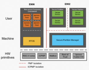
Figure 2-1: TEE system architecture based on PSA specifications
There are three levels of PSA security certification. The following table shows the isolation requirements for each level.
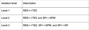
The XuanTie MCU TEE solution incorporates two independent MCU cores from the E series. Firstly, one core runs non-secure code in REE to provide general services. The second core works in TEE to securely boot the system-on-chip (SoC) and provide security-related services.
The heterogeneous dual-core TEE solution has the following benefits:
- Dual-core TEE does not have security requirements for processors and buses. Therefore, it is more appropriate for chip manufacturers, solution providers, and developers, compared to homogeneous solutions. Moreover, time consumption and costs for design and development are greatly reduced.
- The dual-core TEE solution provides higher security due to stronger secure code execution.
- Compared with TrustZone-M, dual-core CPUs support parallel computing, reduce overheads for world switching, and improve overall performance.
- The dual-core TEE solution offers a simplified option for hardware integrity, hence easier use on software.
- This solution allows users to specify MCU cores catering towards their unique business requirements.
2.1 Processor Architecture
The following figure shows the SoC architecture of T-Head’s dual-core solution.
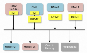
Figure 2-2: TEE system architecture based on XuanTie dual-core MCU architecture
2.1.1 Heterogeneous dual-core MCU architecture
For example, a solution includes two physically isolated MCU cores: XuanTie E902 on TEE, and XuanTie E906 on REE. The physical address spaces of E906 should be restricted by IOPMP units.
An IOPMP unit is a device for memory-mapped I/O. The IOPMP address space is included in the TEE address space. This design ensures proper access control in case of any modification of the IOPMP entries and other master devices. When the secure boot feature is enabled, E902 configures the IOPMP address space to avoid access in REE. After master devices are booted, they cannot access their IOPMP entities or modify the IOPMP access permissions.
The two MCU cores communicate through the Mailbox module. The external IOPMP unit is used to prevent master devices from accessing address spaces in a non-secure manner. Finally, a flexible and secure TEE solution is formed based on the hardware and software co-design.
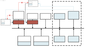
Figure 2-3: IOPMP permission management in the dual-core architecture
2.2 Physical Address Space Protection
According to the PSA security specifications, we must isolate resources and entities with different privileges. in. The following figure shows the architecture of isolation.
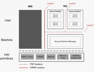
Figure 2-4: Isolation levels based on PSA specifications
In this solution, the IOPMP unit is used to implement the level-1 isolation between REE and TEE. PMP units of E90X MCU cores are used to implement the level-2 isolation between TEE kernel and secure applications, and level-3 isolation between secure applications.
2.2.1 IOPMP
The IOPMP unit is designed for memory access requests, which is initiated by master devices on the bus. After the IOPMP unit completes configuration, other master devices on the bus can no longer be. The IOPMP unit checks whether read and write requests. Only valid requests can be transmitted from the bus to the target devices.
- Deploy an IOPMP unit on a request client
Add an IOPMP unit between each master device and the bus. Each IOPMP unit is independent.

Figure 2-5: IOPMP unit deployment on a request client
Compared with deploying IOPMP units on target clients, the procedure for IOPMP units on request clients is simpler, as it ensures the flexibility of the SoC. Should you need to do so, you must configure the IOPMP units and double-check requested sent from master devices. In this case, you verify that each request includes a master ID. As a result, the design becomes complicated.
2.2.2 PMP
The PMP unit of RISC-V is used to isolate memory access in Machine (M) mode and supervisor (S)/user (U) mode to implement PSA level-2 isolation and PSA level-3 isolation.
![]()
The idea is that you can grant the same access to multiple secure partitions with the possibility of memory sharing. Figure 2-6 shows the shared memory partitions for the secure partitions.
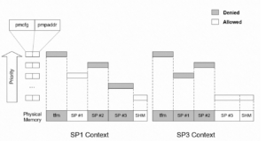
Figure 2-6: PMP configurations for different secure partitions (level-3)
2.2.3 Interrupt Controllers
In the XuanTie MCU TEE architecture, each MCU core has an independent core local interrupt controller (CLIC) for physical isolation. When you design an SoC, you need only to connect peripheral devices to the corresponding interrupt controllers. For example, you can connect secure peripheral devices to the CLIC in TEE, and connect non-secure peripheral devices to the CLIC in REE. This way, interrupts are isolated between REE and TEE. To implement such isolation, IOPMP units must be configured to prevent entities access mismatch.
3. Conclusion
We have discussed in details in this article the implementation of the TEE solution based on the XuanTie dual-core RISC-V architecture. The solution meets the requirements of PSA Certified Level-1, Level-2, and Level-3 and is acceptable for chip manufacturers, solution providers, and developers. The main benefit is that this design helps reduce design and development costs. Lastly, it also allows users to configure MCU cores based on their business requirements.


